") English (United Kingdom)
English (United Kingdom) ") Hindi (India)
Hindi (India) ") 한국어 (Korean)
한국어 (Korean) ") Português do Brasil (pt-BR)
Português do Brasil (pt-BR)  Български
 ") Deutsch (Deutschland)
Deutsch (Deutschland) ") Italiano (Italia)
Italiano (Italia) ") Português de Portugal (pt-PT)
Português de Portugal (pt-PT) ") Română (România)
Română (România) ") Español (España)
Español (España) ") Türkçe (Türkiye)
Türkçe (Türkiye) ") Français (France)
Français (France) ") Greek (Greece)
Greek (Greece)
 |
HEATING VENTILATION &AIR-CONDITIONING DESIGN |
||||||
|
|
|||||||
|
FineHVAC combines Design and Calculations in a Fully Integrated Environment, performing all the required calculations for any HVAC Installation directly from the drawings, generating all the study results: Calculation sheets, technical reports, bill of materials and costing, as well as all the final drawings (plan views, panel diagrams, details) fully updated. A new BIM design on top of the latest ITC and ODA libraries ensures unrivaled performances at any level (i.e. display engine, open/save & read/write functions, performance of sophisticated algorithms etc). FineHVAC includes a series of advanced modelling features, such as the intelligent BIM objects and their quick editing, the intelligent building level/floor management, the clash detection while designing the HVAC/Plumbing/Electrical networks, the visual 3D model for the heating/cooling surfaces of the building shell, the option for real time editing of the network diameters/sizes (i.e. desired dimensions) through the Property Panel, the smart algorithms in the Air Ducts module to generate the detailed 3D realistic model according to the Ashrae detailed guidelines, the real time 3D sizing of the heating/cooling units (following the requirements and the manufacturers’ data) the integration of the 3D building services installation drawings within the 3D architectural model, the high quality fast rendering to create realistic views of both, the building shell and the MEP installations (piping network, air-duct network etc) and many others. And over all, FineHVAC ensures a full BIM Compatibility and Interoperability with any BIM application (i.e. Revit, Archicad etc) via the IFC and/or RVT files and seamless integration among the FINE-MEP verticals, as well as with IDEA and FineGREEN. > e-shop |
|||||||
|
New FineHVAC 24 Major Upgrade with additional advanced features
What's new on FineHVAC24 I. CAD Component I.1 CAD Component – New Features in General General > Total redesign of the FINE CAD engine on top of the latest 4MCAD core, based on the latest ITC and ODA libraries, on a BIM philosophy and 64bit architecture. > Unrivaled CAD performance compared to the previous FINE19 version, as a result of the above redesign and a multitude of new design tools and facilities > Reading of Revit files (rvt format) for open communication with the most widespread BIM files. Interface > New updated interface identical to Autocad > Capability to display ribbon and menubar simultaneously > Tool palettes > Significantly faster zoom/pan speeds (upgraded display engine) > Faster reading/writing and opening/saving files > Noticeably higher performance in both AutoBLD & AutoNET command groups thanks to the new design engine (3 generations higher than that of FINE19) > Enriched AutoBLD & AutoNET dialogs > Increased supervision with display of underlying and superimposed floor outline Plot > Ability to import points directly from a file or external reference to create a 3D or 2D plot > New 2D plot definition dialog with the ability to define from a polyline or 3D plot. > New 3D plot editing dialog with the ability to create excavations. Building Shell (AutoBLD) > Reading Revit (Rvt) files for the building shell (beyond IFC/BIM reading capabilities) > Creating and Editing Curtain Walls with all their characteristics > Creating a Multiple Opening (rectangular opening consisting of horizontal and vertical repetitions of the opening selected from the program library) > Ability to place Blinds - analytical calculation of shadows > Ability to place 3D horizontal cantilevers - analytical calculation of shadows > Ability to place an inclined cantilever - analytical calculation of shadows > New “matchproperties” command for all entities of the building shell (and networks) for direct copying of properties from one entity to another, individually or in bulk and for one or more characteristics > Connection-union of columns with roof (beyond the connection of walls with roof) > Calculation of Thermal Bridge of a sloping wall surface in case of connection with a roof > Display of Thermal Bridge sides and possibility of inversion with one click > Capability to define a Different Thermal Bridge between column and beam > Capability to define Building Elements directly from the FINE design tool > Capability to define values for Ventilation, Space, People, Devices, Lighting Elements directly from the FINE design tool with easy copying-editing per space > Capability to define typical space elements > Increased supervision during the configuration of the shell having the outline of the underlying and superimposed floor > Integrated cooperation with the new IDEA24 and FineGREEN24 Networks (AutoNET) > Capability to define and modify Network Elements directly from the FINE design tool for all E/M Installation networks > Selection of elements from libraries with search capability via words as well, for faster finding of the desired elements of the library contents > Indication of heating data in the floor plan update in Fan Coils (with FCU type display etc.) > Detailed axonometric diagrams (underfloor, air ducts etc)
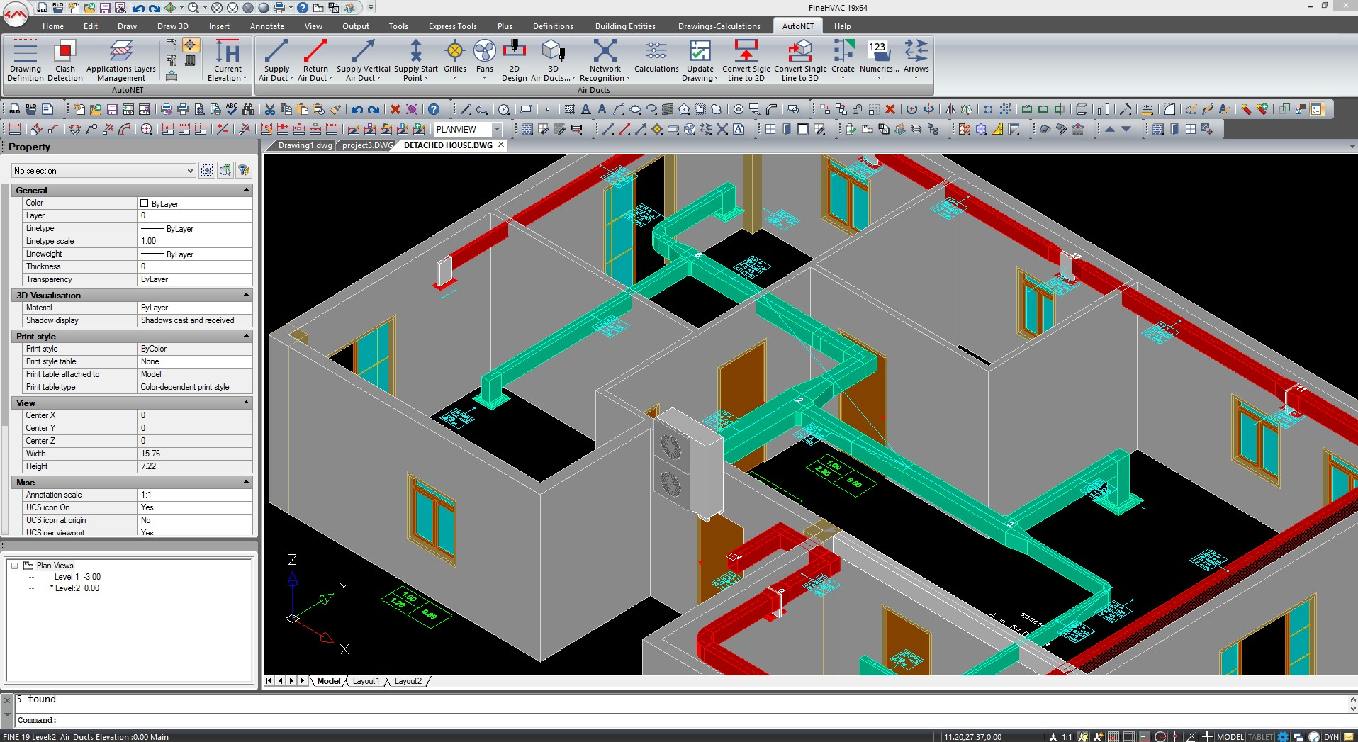
I.2 CAD Component – New Features per Application HEATING LOSSES – COOLING LOADS > Ability to define Building Elements directly from the FINE design (indoor and outdoor temperatures - city climate data, room conditions, etc. parameters) for immediate supervision > Ability to define Space Elements for Ventilation, People, Devices and Lighting elements directly from the FINE design with easy copying-editing per space > Faster operations in the design and identification of spaces as well as in updating them with the results of the calculations UNDERFLOOR HEATING > Design of underfloor network in an upgraded environment-interface of high ergonomics and functionality, with a multitude of new tools > Faster network design and creation of floor plans and 3D thanks to the major upgrade of the design engine > Capability to identify the network for automatic update of the calculations > Capability to design normalized circuit pipes > Capability to define an underfloor system directly from space > Capability to design a clockwise and counterclockwise circuit > Capability to define Usage and thermal resistance directly from the circuit > Update circuit length during design > Update Floor Plans > Design a different vertical for the case of a meander - snail > Design an Axonometric diagram > Convert a 2D floor plan to a 3D drawing based on calculations FAN COILS > Update Floor Plans with detailed display of heating data (with display of FCU type etc.) > Automatic recording of circulators even at more than one starting point (network beginnings) AIR DUCTS > Create an Axonometric Diagram with details > Automatic fan mapping even at more than one starting point (network origins
II. Calculation Component II.1 Calculation Component – New Features in General General > Redesign of the computing core with 64bit Architecture resulting in impressively higher calculation speeds in the calculation sheets of the ADAPT applications > Renewed Interface (GUI) environment with Ribbon menus, icon bars and advanced ergonomics > New libraries on an advanced platform (Firebird instead of Access), for friendlier management and better performances > Heat pump selection, analytically based on the efficiency curves in Heating-Air Conditioning > Inverter circulator selection with analytical hydraulic solving, in Heating-Air Conditioning installation networks > Analytical pre-measurement of components per pipe diameter, in piping networks > Even more analytical and detailed pre-measurements in all installation networks through the analysis of all individual subsections of each section (e.g. L=2+3+1+0.7 m) > Large expansion of network calculation sheets (up to 4,500 network sections per file design) for even larger projects. > Analytical calculation of U-factors of structural elements (walls, floors, etc.) through the selection of successive layers from the new library of building materials.
II.2 Calculation Component – New Features per Application HEATING LOSSES > Renewed Interface environment with Ribbon menus, icon bars and advanced ergonomics > Analytical calculation of thermal transmittance coefficients (U factor) of structural elements > Upgrade of libraries on a new advanced platform > Dealing with various special cases (e.g. "floor to pilotis" option) TWIN PIPE HEATING > Renewed Interface environment with Ribbon menus, icon bars and advanced ergonomics > Capability to select a heat pump in detail > Analytical pre-measurement of components by pipe diameter > Detailed pre-measurements with full analysis of individual pipe sections > Selection of Inverter circulators with hydraulic analytical solving > Upgrade of libraries on a new advanced platform > Calculation sheets with a double capacity for even larger installations SINGLE PIPE HEATING > Renewed environment Interface with Ribbon menus, icon bars and advanced ergonomics > Independent networks in the same study > Capability to select a heat pump in detail > Detailed pre-measurements with full analysis of individual pipe sections > Selection of Inverter circulators with hydraulic analytical solving > Upgrade of libraries on a new advanced platform UNDERFLOOR HEATING-COOLING > Renewed Interface environment with Ribbon menus, icon bars and advanced ergonomics > Calculations according to EN1264-2 2021 > Calculations also for Cooling (Cooling) > Independent networks in the same study > "Network controls" window, for controlling supply temperatures in heating and cooling (e.g. Heating 40 - cooling 17) > Calculation of thermal efficiency from passing pipes > Calculations with desired floor temperature in each case > Capability to select a heat pump in detail > Analytical pre-measurement of components by pipe diameter > Detailed pre-measurements with full analysis of individual pipe sections > Selection of Inverter circulators with hydraulic analytical solving > Library upgrade on a new advanced platform COOLING LOADS > Renewed Interface environment with Ribbon menus, icon bars and advanced ergonomics > Latest RTS 2021 method > Analytical calculation of u-factor of structural elements > Dealing with various special cases (e.g. floor to pilotis selection) > Display of Maximum loads of rooms with Ventilation in the "Windows" printer (not only in design printers). > Ventilation calculation with both per-person and per-air volume changes > Ventilation recovery coefficient in case we skip Psychrometry and go directly to VRV unit selection > Adding LED lights to the lighting libraries > Upgrading libraries on a new advanced platform FAN COILS > Renewed Interface environment with Ribbon menus, icon bars and advanced ergonomics > Possibility for different types of Fan Coil in the same study > Pre-measurement of components by pipe diameter > Possibility of defining many independent individual units (as in the two-pipe) > Detailed pre-measurements with full analysis of individual pipe sections > Selection of Inverter circulators with hydraulic analytical solving > In the Fan Coils libraries, elements for heating as well > Heating Possibility of selecting a heat pump > Pre-measurement of components by diameter pipe > Library upgrade on a new advanced platform > Calculation sheets with a double capacity for even larger installations AIR DUCTS > Renewed Interface environment with Ribbon menus, icon bars and advanced ergonomics > Detailed pre-measurements with full analysis of individual air duct sections > Library upgrade on a new advanced platform > Calculation sheets with a double capacity for even larger installations PSYCHROMETRY > Renewed Interface environment with Ribbon menus, icon bars and advanced ergonomics
|
|||||||
FineHVAC Features & Highlights
EASY TRANSITION |
||||||
|
The easiest transition for Engineers coming from AutoCAD Our MEP Software includes all the features of 4MCAD, our alternative to AutoCAD®. You get 2 software in one, you can keep using CAD to edit some DWG drawings. |
||||||
|
In Fine HVAC you can create your BIM project in 2D or 3D using very simple 2D commands any CAD user knows like polylines, entity snaps, copy... Fine HVAC combines an AutoCAD-like look and feel and an advanced BIM technology that will help you to draw your project and networks. |
||||||
|
Draw the building like in 2D and get the 3D Drawing the building in 3D with BIM objects is required to calculate the Thermal losses and Cooling loads but Fine HVAC will help you to do it in just a few clicks. You just need to focus on floor plans using the intelligent and parametric objects of the AutoBLD menu and Fine HVAC will build the 3D for you. A simple double-click on any object will display its properties for modification. You have all the required tools to create or modify the BIM model without using any other external software. Alternatively you can also open a project created with any other 4M BIM Software and will not have to draw the building. You may for example open a project created with IDEA Architecture and will just have to define the spaces before proceeding to calculation (See video). Unrivaled Compatibility with AutoCAD Unlike other BIM MEP Software, Fine HVAC uses DWG as its native file format and includes features to convert the 3D BIM objects into simple vectors that can be further edited in AutoCAD®. Sharing 2D or 3D files with other professionals is therefore much easier. Includes a full CAD Software ">Our MEP Software includes all the features of 4MCAD , our alternative to AutoCAD®. You get 2 software in one, you can keep using CAD to edit some DWG drawings.
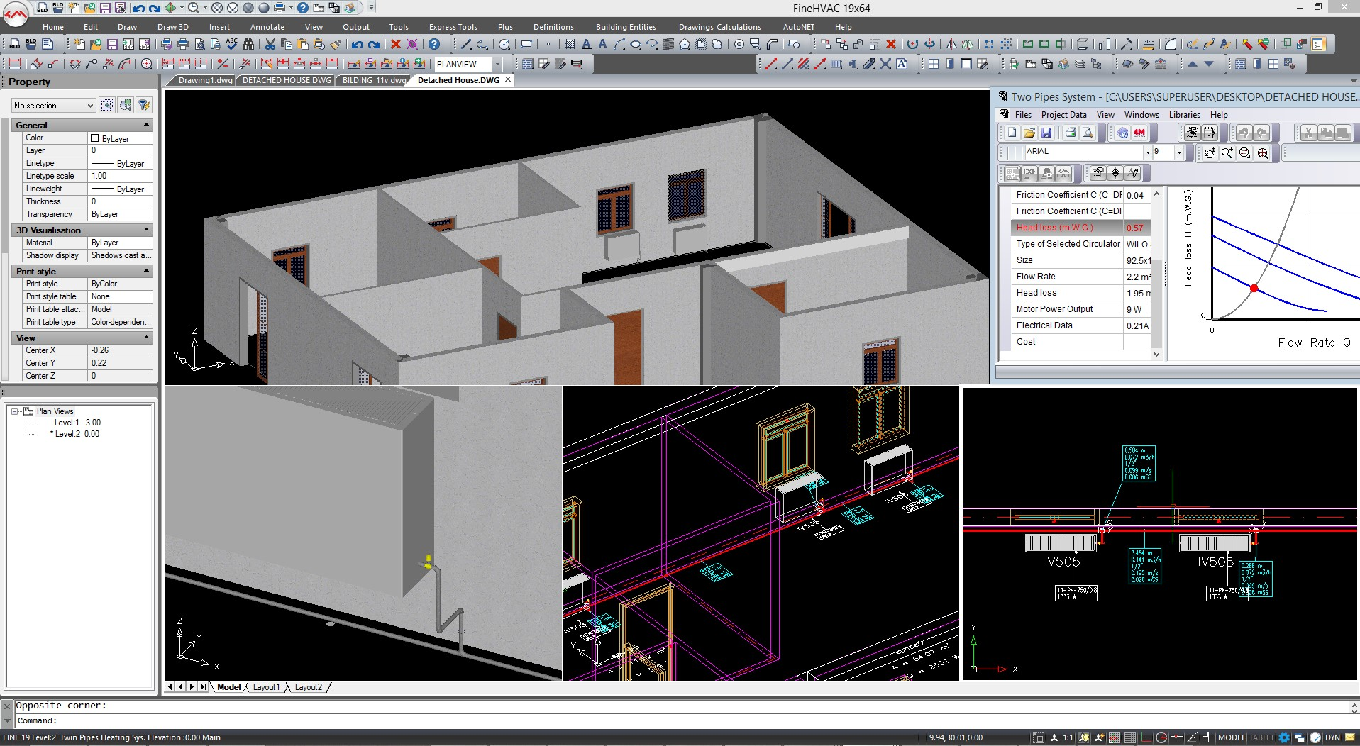
NETWORKSIntelligent Network Design Unlike in other BIM software, Fine HVAC's advanced and very intuitive BIM technology does not come at the expense of speed, it is just the opposite: you just need to draw a few single lines and the software will do the rest. Assisted Placement of Receiptors Fine HVAC automatically locates on the view plan the respective installation components (i.e. heating units, fan coil units, air-duct grills etc), through several expert rules that consider among others, the user's preferences (e.g. radiator preference order, window height control, limit for additional radiator etc). Piping Networks Aurorouting At this stage of the project, the pipes just need to be drawn as single lines. Commands like "Double Pipe" (e.g. induction - return), "Parallel to Wall" or "Parallel to Points" accelerate significantly the installation drawing while all connections are automatically created through the "magic" autorouting commands (e.g. 2-3 movements are enough to connect a group of grills to the vertical airduct column). |
||||||
|
Updating Drawing from Calculation After performing the calculations you can update the drawing from the calculation and Fine HVAC will convert the single lines into 2D pipes. Pipes sizes will be deducted from the calculation results. Symbols and Designations (e.g. Single-Pipe System arrows, junction points - pipe connection circles, column direction arrows, up-down legends, comments etc) are also automatically inserted, perfecting the project drawings. |
||||||
|
|
||||||
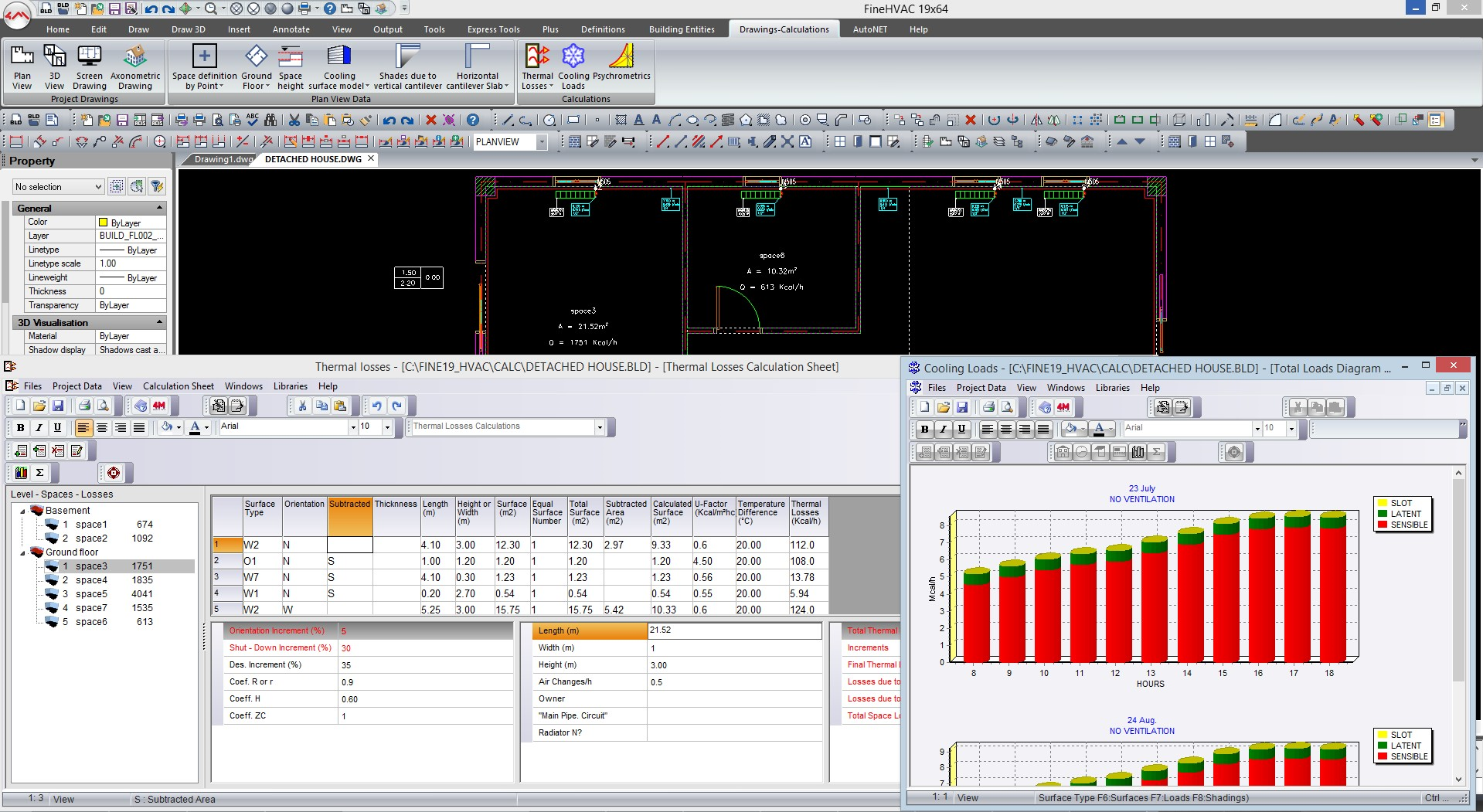
CALCULATIONSThermal Losses, Cooling Loads Fine HVAC's Calculation module is closely interacting with the BIM model. You can calculate the thermal losses, cooling loads and heating insulation from the drawing and will update the drawing with the results of the calculations. Calculate from the drawing Fine HVAC's Calculation module will read the physical properties of the BIM objects in your project to calculate the thermal losses and cooling loads space by space. It will also recognize the networks and receptors you designed and help you to calculate the air-ducts and pipes taking into consideration flow rates, pressure drops and more. Results are sent back to the drawing and exported in a calculation report you can customize. Choose the Standards required Following the International Standards and Regulations, Fine HVAC enables the user to select the applying methodology. In each case, the package utilizes the more advanced techniques and mathematical models for maximum accuracy, speed and reliability in calculations (e.g. analytical system of psychrometry equations, model of hydraulic simulation etc.): |
||||||
| > | Cooling loads : Carrier - Ashrae CLTD - Ashrae TFM - Ashrae RTS | |||||
| > | Thermal losses : EN 12831, DIN 4701 and Ashrae | |||||
| > | Air-ducts : Equal Velocities - Equal Pressures - Static Regain | |||||
2D/3D OUTPUTSGet all the technical drawings from the Project and calculation After proceeding to the design of the network and calculations our MEP Software will let you generate all the technical drawings and reports you need. Vertical Diagram Our MEP Software will generate for you the vertical diagram of the project in a DWG drawing you can further modify and/or share. Technical Reports & BoM |
||||||
|
Fine HVAC will generate a document with the calculation results and the bill of materials describing the quantities of each of the elements required to build the HVAC systems. The template of this document can be customized and you can chose which results you want to display. Project Drawings The BIM model of the Building will be updated with the results of calculation to define the size of the pipes and air-ducts but also with symbols and designations. As a result you will be able to generate floor plans in DWG showing all the receptors and networks you have defined. |
||||||
|
|
||||||
BIMFeel the power of BIM Software 4M is a pioneer of BIM with a complete suite of BIM Software for Architecture & Engineering initiated in 1993. The 4M BIM Software are renown by experts to be the BIM software offering the easiest migration for AutoCAD users as they are the only ones to use DWG as their native file format and an AutoCAD-like look-and-feel. BIM Design & Collaboration in FineHVAC Fine HVAC's advanced BIM technology will increase your productivity. Using our smart 3D modelers and libraries of 3D BIM objects you will be able to draw the building much faster and easier. The close interaction of our Calculation module with the BIM model will help you to make all the calculations directly from the model. Fine HVAC will simply read the BIM model to understand the project, the physical properties of the BIM objects (U factor), proceed to calculations and finally update the drawings with the calculations results. Last but not least you will be able to collaborate with other BIM software and share with other architects and engineers the discipline-specific contents you added to the common BIM project. Bill of Materials The BIM information can also be extracted to create a Bill of Materials showing the quantities and surfaces of the various materials and fittings you created in the building. You can calculate the cost and get a detailed description of the steel sheets you need. |
||||||